Synchro Transmitter/Receiver Test Set

|
This project comprises a synchro transmitter / receiver and includes an in-built reference oscillator capable of providing a 26V RMS (74Vpp) 400Hz excitation signal. The transmitter and receiver are completely separate circuits and may be operated independently or simultaneously. The internal reference may be disabled and an external signal applied if required. Receiver:
Transmitter:
Excitation:
|
Block diagram: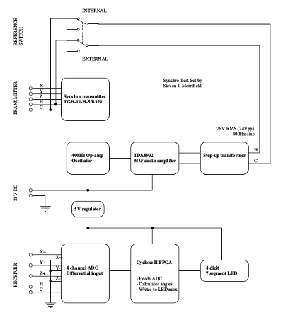 |
Amplifier:
| Oscillator:
| |
0 degrees: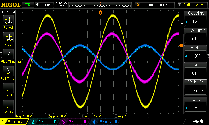 |
90 degrees: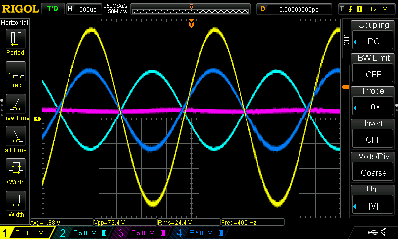
| 180 degrees: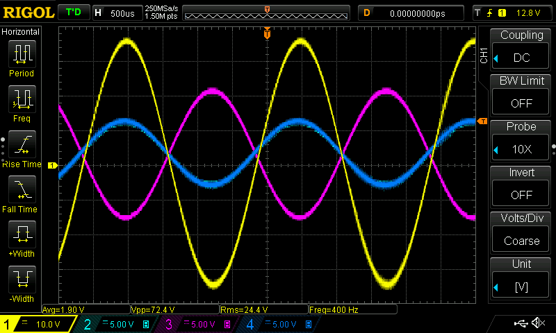
| 270 degrees: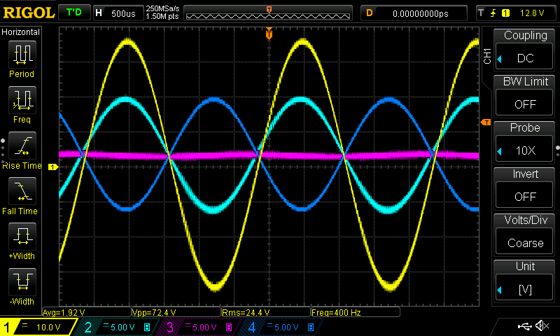
|