Programmable Dual Channel DC Power Supply
|
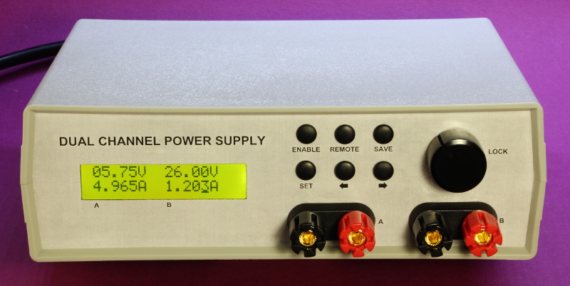
This project involved the design and construction of a programmable, dual-channel DC power supply. Each channel is independently capable of being set from 0.00 to 30.00V with a resolution of 1.25mV. Current limiting may be set from 0.000 to 5.000A with a high-side measurement resolution of 0.15mA. Display resolution via the LCD is 10mV and 1mA. Full floating-point precision is available via a remote PC connection.
Specification overview:
The design is modular featuring a COTS AC-DC converter for efficiency with a dedicated micro-controller PCB and separate power supply PCBs for each channel. This minimizes noise between channels as well as improving reliability and maintainability. Each board is wired using a star-ground methodology. Right-click to open larger images. |
Micro-controller boardPIC 18F4550 with interfaces for 16x2 LCD, 6 switch keypad, rotary encoder, I2C DAC, I2C current/voltage monitor, PC UART & USB, PWM buzzer, internal EEPROM, ICP. |
 |

|
Power supply moduleLM2596 switching regulator with low pass filter. Separate low-noise linear 5V regulator for MCP4725 DAC and INA226 high side power monitor. This module interfaces with the micro-controller board via I2C. Two of these boards are used with different I2C address configurations. |
 |

|
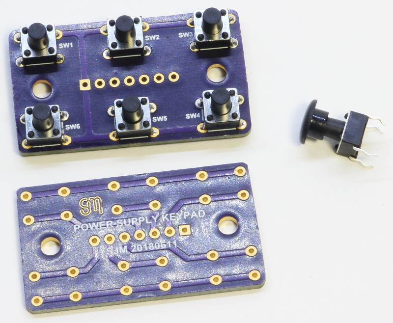
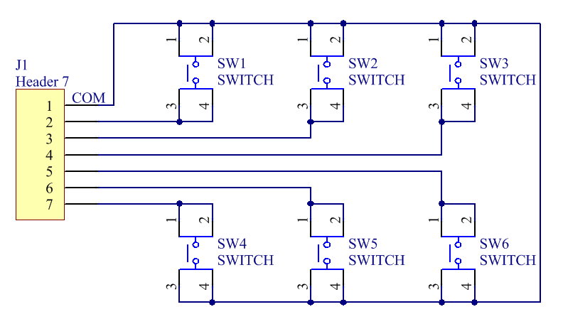
KeypadA simple keypad that allows the user to control various settings. Interfaces directly to the micro-controller board via GPIO pins. Standard through-hole 6x6 tactile switches are used with push-on plastic knobs. |
 |
|
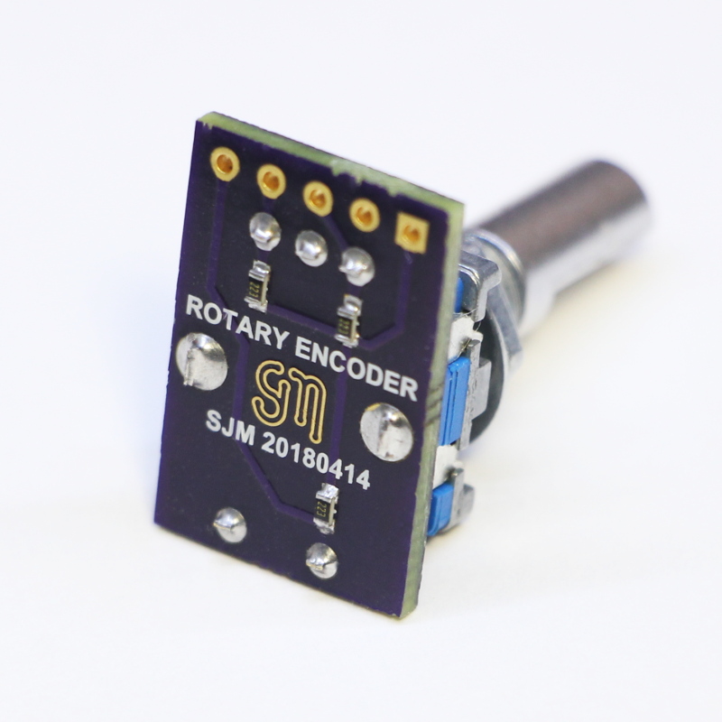
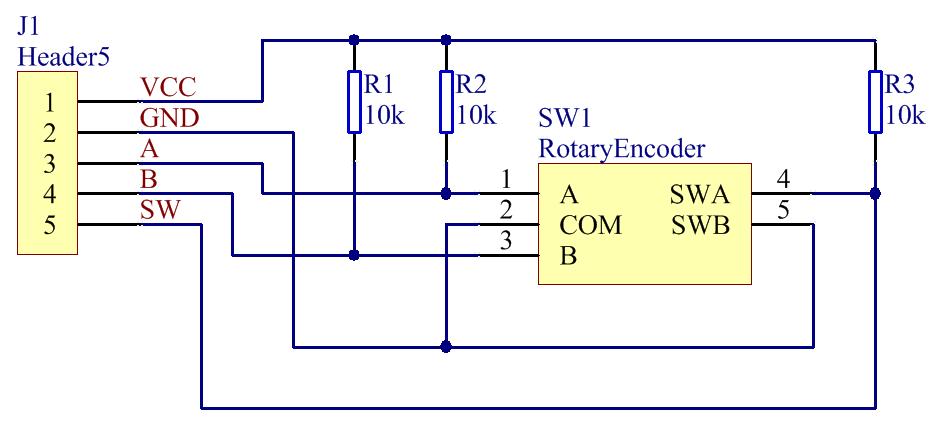
Rotary encoderA simple rotary encoder allows the voltage and current settings to be adjusted up and down. The rate of change varies depending on the cursor position with steps ranging from 10mV/1mA to 10V/1A per step. Pressing and holding the encoder button locks all keys preventing inadvertent adjustment. |
 |
|
Software features
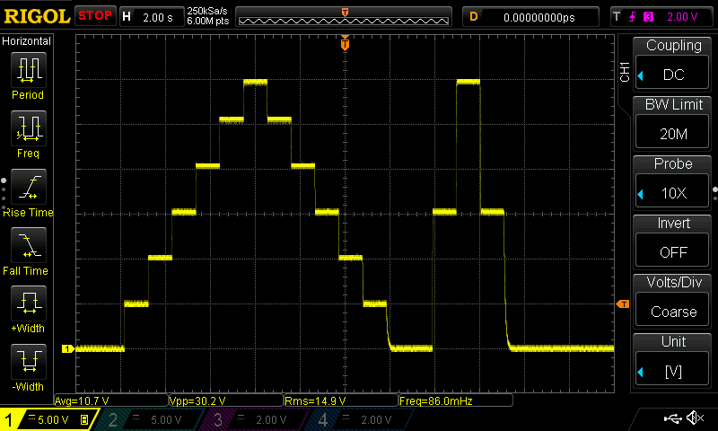
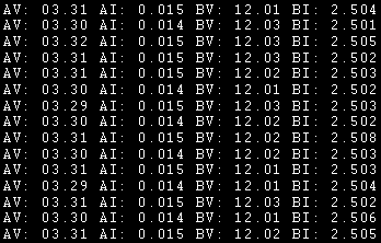
These screenshots shows how a remote PC connection can be used to generate programmable voltages and demonstrates a typical example of logging voltage and current to a file. |
 |
|
|
PC serial protocol: 19200, N81 To enable/disable real-time logging of all parameters, send 'L'.
To set voltage or current parameters, each command from the PC must comprise of 6 characters: |
Construction |
Internal view from the front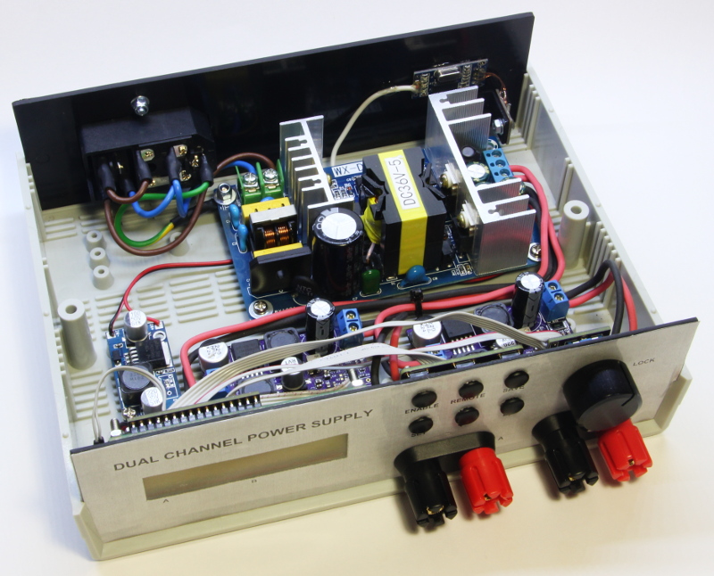
| Internal view from the rear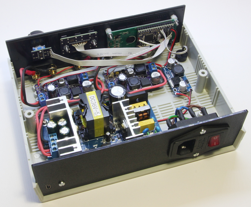 |
Proof of concept prototype - top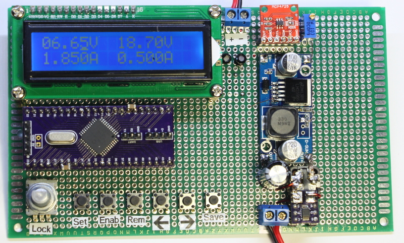 |
Proof of concept prototype - bottom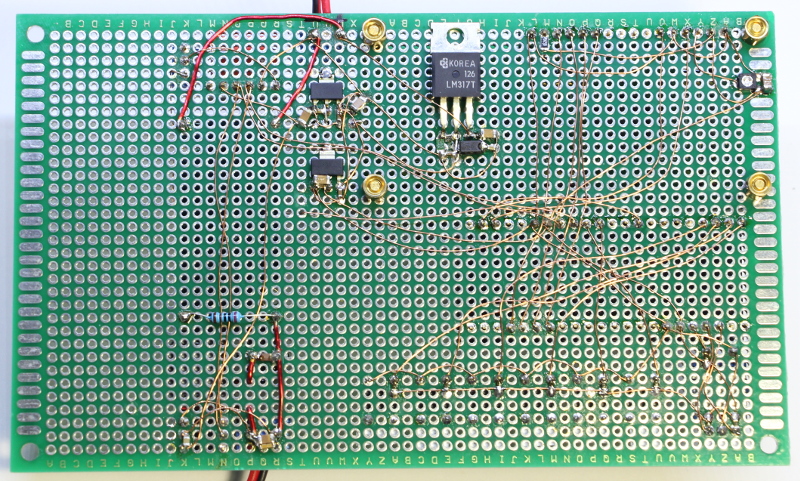
|
Milling the front panel on my homemade CNC mill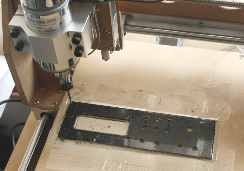 |
Turning the LCD and keypad standoffs on my lathe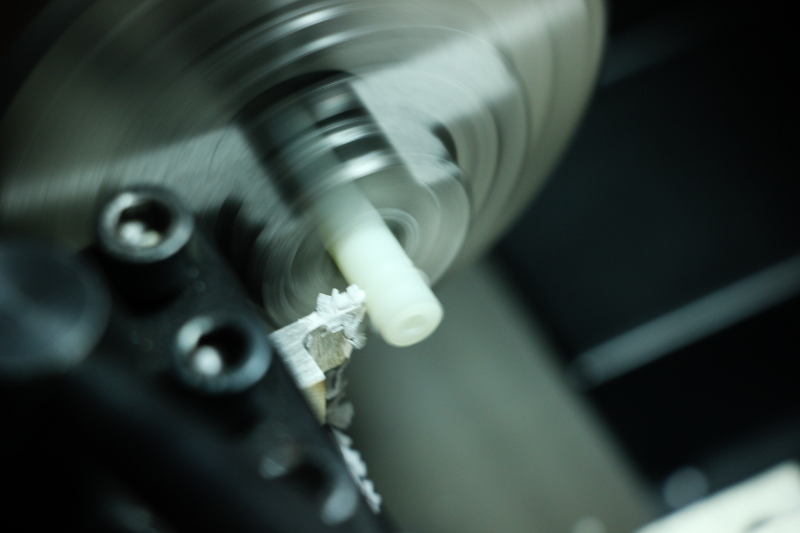
|